Materials
|
-Arduino Uno
-Motor controller -Wheels + Motors + Gearbox -Creo Parametric 2.0 -MakerBot Replicator 2 -Hand drills -Files -Vice grip -Jack -Calipers -Hammers -Ultrasonic Sensors -Limit Switches -Wires |
|
Methods
|
The methods used in the creation of the robot followed a design process (shown in writing 4.2) that helped organize the process of each individual part. What we decided was important was the area in front of the robot in relation to height, and in relation to walls. Knowing the height of the area in front of robot is very important because of the problem of falling, high centering, and flipping over. Knowing what was directly in front is also important because the robot must not get stuck on a wall driving into it. All mounts were created using Creo 2.0 and then exporting the model into a 3d printer (MakerBot Replicator 2) using PLA plastic with a 15% infill (not solid).
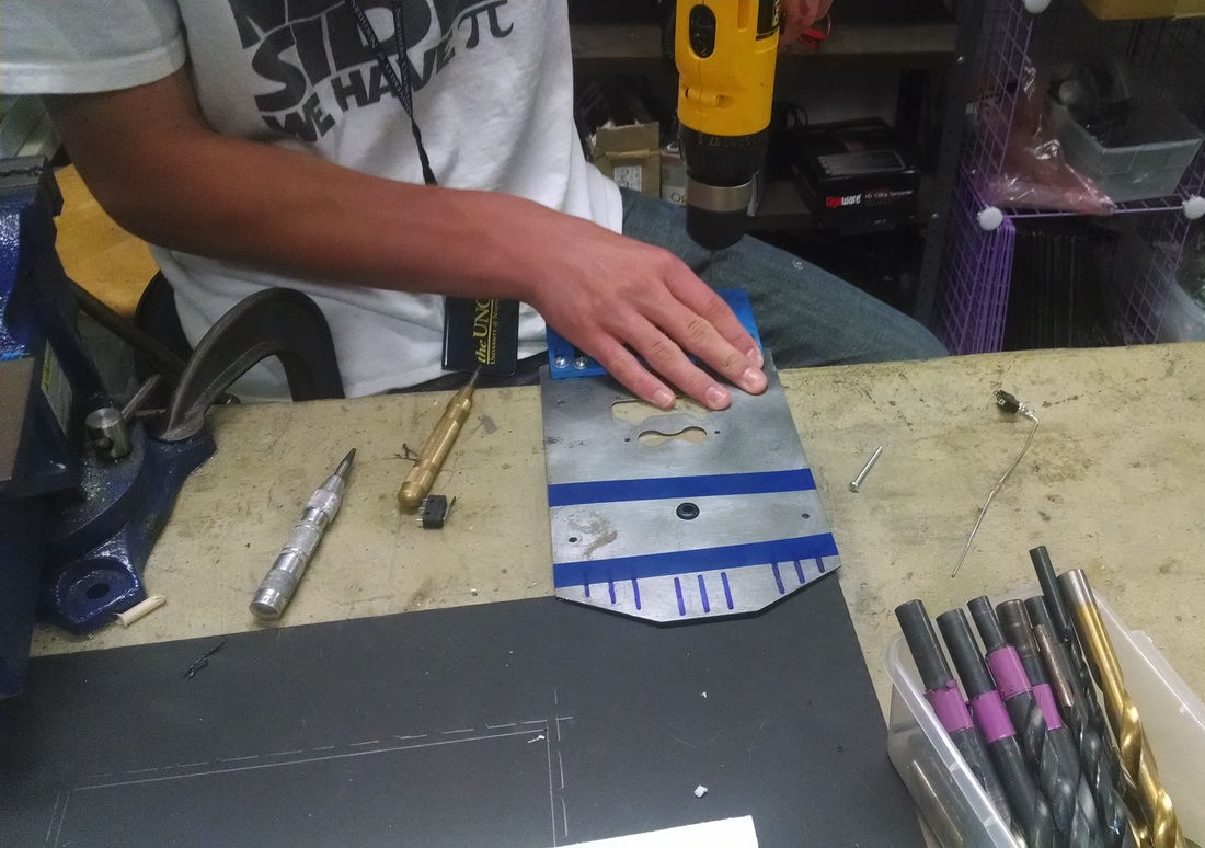
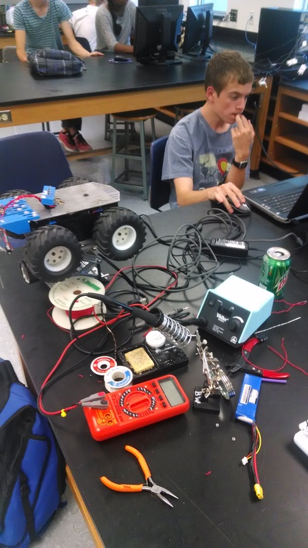
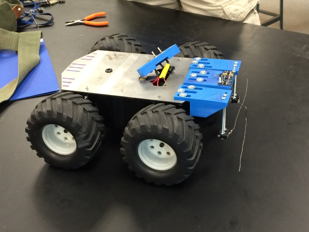
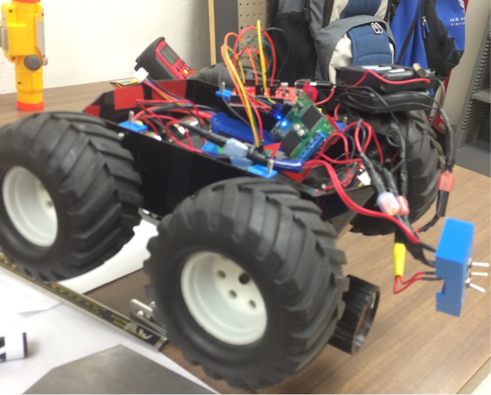
MouseBot Chassis The chassis was used from the LAZARUS project and included motors and gearboxes. As well as the switches to turn the motors off and on. What we modified was the metal top so that it may have holes to accommodate our sensors. The chassis is used because of the need for movement and control for the robot as well as being the base on which the sensors are to be mounted. With its wheels and motor controller, the robot can maneuver around a variety of rough terrain. The front and back of the robot are angled inward (70 degrees) so the design of the mounts has to include a triangle and the sides are angled at a 45 degree relative to the sides. The angles present on the chassis must be included into the mount designs as it must be strong enough so that the mounts can take trauma. The inside of the robot also provide a copious amount of space for electronics to fit in such as the Arduino Uno as well as a printed circuit board. Ultrasonic (also named parallax ping sensor) Mount The ultrasonic sensor was installed because the robot needed a way of detecting topography. It works by sending a high pitched sound and measuring the difference when it bounces back. The ultrasonic was put out in front so that it could not cross interfere with itself and to make sure the robot can stop once the ultrasonic found a point where the robot cannot pass. The range the robot can drive through is between 3.5 inches and 4.5 inches, so the ultrasonic has to measure this constantly to make sure the robot does not fail (Figure 3.) . Slots were made in the back so it could be adjustable with the ability to slide in and out. Limit Switches Mounts The limit switches were installed because the robot needed a way of detecting obstacles. They work by a spring loaded trigger that either makes or breaks a circuit. Two were implemented because we needed to know if the obstacle was to the left, to the right, or in the center so that the robot can turn accordingly. It was built sturdy with more mass than the other mount so that it can absorb most of the shock of driving into a wall as these mounts were to be used a mechanical stops. They were also digital stops telling the robot there is a wall in front. Long bolts were used to mount the limit switches as low as 1.5 inches of the ground so the robot can detect if there is any obstacle lower than the center of the wheels (Figure 5.). Slots were also used so that it adjustable but were angled due to the way it is mounted. Electronics The electronics had to planned along the way making sure it made logical sense. The arduino uno was capable of analog in, and digital outputs and inputs. We only got to use the digital pins for the sensors. Simple soldering was done to connect the leads into the arduino (soldering the tips). For the limit switches a pull up resistor was made for both using a small printed circuit board. The leads for the ultrasonic sensor were solder on then using the instructions on the ultrasonic, connected accordingly. Design Process Every idea had to through a process to make sure it could achieve its goal. The first step was to get the idea for a mount. Ideas came from the need to have spatial awareness for the robot, so current rovers designs were evaluated to see what each sensor did. The challenge was broken down to manageable pieces, each with their own tasks to accomplish (i.e. how to not flip over) and we evaluate each one and decided on a plan of action. A whiteboard drawing was made so that other teammates could pitch in their ideas. Once it matured we then modeled it in CREO and attached it to the robot to see how it would function. We then refined the idea and present it to the team, which then discussed if it was acceptable. If it waS declined then we archived the progress done so that if we were to revisit it we would not need to make the same tests. If it passes then the print would be exported, made, and installed onto the robot. Design Notebook Every idea we had was put into a notebook along with the planned specifications. The notebook contained a detailed explanation on the purpose of each design, were it would be put, and the general shape. Along with the purpose we recorded the materials need to build this object. Then we observed points of failure that could occur when using the item evaluating if it would not work. The electronics were sketch alongside. Programming involvement was also crucial if we were to bring all aspects of the robot together. |
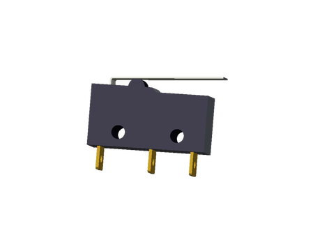
Limit Switch
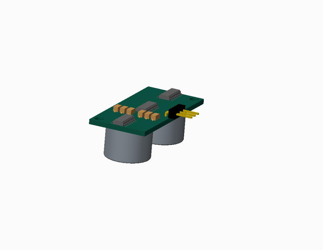
Ultrasonic Sensor
|
